MIT6.828-2018
本课程课程主要以xv6为例子进行讲解,会有xv6相关的作业,但lab为实现一个自己的JOS。JOS与xv6类似,但两者在某些方面有不同的设计思路。
环境配置
下载课程所需的源码:
安装依赖
1
|
sudo apt-get install build-essential gdb gcc-multilib
|
安装qemu
首先进行配置,配置需要python2.X环境,需指定python2.X可执行文件的位置,如
1
|
./configure --disable-kvm --target-list="i386-softmmu x86_64-softmmu" --python=python2.7
|
之后编译安装
1
2
|
make
sudo make install
|
编译过程中可能出现一些问题, 如需要在 qga/commands-posix.c 的 <sys/types.h> 头文件后面加 <sys/sysmacros.h>。
编译过程中出现的-Werror=XXX的错误可通过在config-host.mak中的QEMU_CFLAGS后添加对应的Wno-XXX解决。注意config-host.mak是由./configure生成的文件,修改QEMU_CFLAGS后不要重新./configure。
编译并启动JOS
在JOS源码目录下
即可在命令行和新窗口中同时启动JOS操作系统。GNUMakefile中还定义了许多方便我们调试的phony targets,详细信息以及gdb, qemu调试技巧参考6.828 lab tools guide。
编译运行xv6的过程类似。
Lab 1: Booting a PC
Part 1: PC Bootstrap
物理内存空间
32位机的物理内存空间通常有如下布局:
1
2
3
4
5
6
7
8
9
10
11
12
13
14
15
16
17
18
19
20
21
22
23
24
25
26
27
28
29
30
|
+------------------+  <- 0xFFFFFFFF (4GB)
|      32-bit      |
|  memory mapped   |
|     devices      |
|                  |
/\/\/\/\/\/\/\/\/\/\

/\/\/\/\/\/\/\/\/\/\
|                  |
|      Unused      |
|                  |
+------------------+  <- depends on amount of RAM
|                  |
|                  |
| Extended Memory  |
|                  |
|                  |
+------------------+  <- 0x00100000 (1MB)
|     BIOS ROM     |
+------------------+  <- 0x000F0000 (960KB)
|  16-bit devices, |
|  expansion ROMs  |
+------------------+  <- 0x000C0000 (768KB)
|   VGA Display    |
+------------------+  <- 0x000A0000 (640KB)
|                  |
|    Low Memory    |
|                  |
+------------------+  <- 0x00000000
|
Part 2: The Boot Loader
BIOS运行过程中,首先设定了中断描述符表,对VGA显示器等设备进行了初始化。在初始化完PCI总线和所有BIOS负责的重要设备后,它就开始搜索软盘、硬盘、或是CD-ROM等可启动的设备。最终,当它找到可引导磁盘时,BIOS从磁盘读取引导加载程序并将控制权转移给它。
JOS使用传统的硬盘启动机制,这意味着boot loader必须满足于512字节。BIOS将boot.S这段代码从硬盘的第一个扇区load到物理地址为0x7c00的位置,同时CPU工作在实模式。
x86下的寻址模式
x86下的寻址模式包括实模式和保护模式。在实模式下采用分段的方式,程序中的一个地址通过CS:IP的模式进行解释,CS为段地址,IP为偏移地址。其表示的物理地址通过CS*16+IP计算得出。
而在保护模式下则采用分段与分页相结合的寻址方式,总体示意图如下图所示:
1
2
3
4
5
6
7
8
|
           Selector  +--------------+         +-----------+
          ---------->|              |         |           |
                     | Segmentation |         |  Paging   |
Software             |              |-------->|           |---------->  RAM
            Offset   |  Mechanism   |         | Mechanism |
          ---------->|              |         |           |
                     +--------------+         +-----------+
            Logical                   Linear                Physical
|
对于一个logical address,它首先会根据分段机制翻译为linear address,之后再根据分页机制将该linear address翻译为真正的physical address。
详细的翻译过程与表项结构如下图所示:
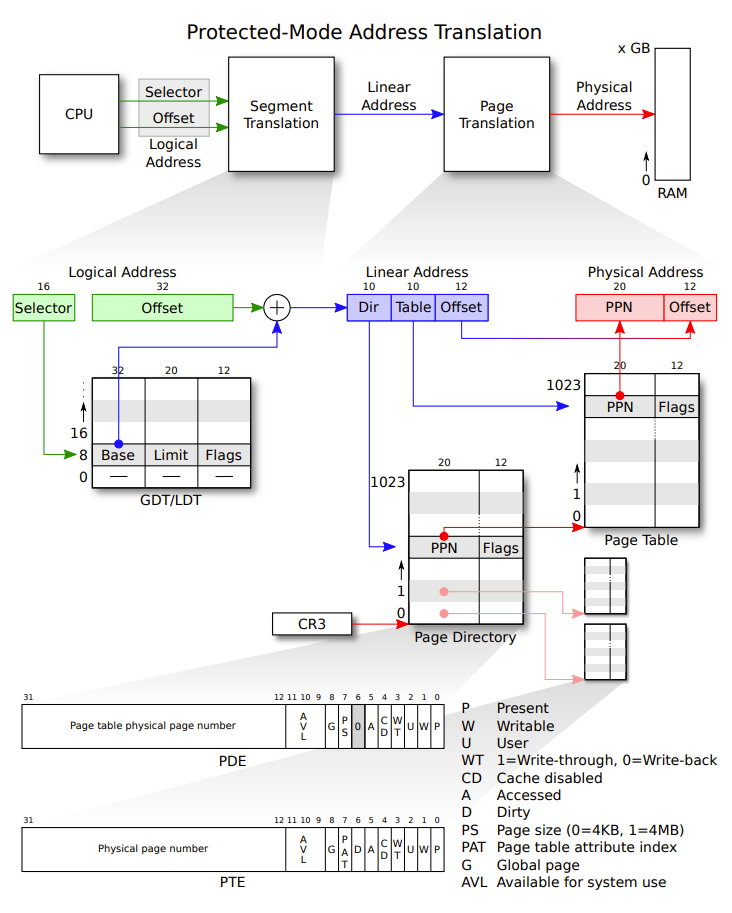
从logical address到linear address的翻译采用分段的方式,它将一个logical address解释为selector+offset,并根据selector找到段描述表中对应的表项,该表项存了放每个分段的相关信息(段起始,段长,标志),检查权限后根据段基址base和偏移offset得到linear address。从linear address到physical address的翻译采两级页表的分页方式,这个两级页表的维护将由我们在lab2中完成。
需要注意的是上述地址翻译的过程都是MMU由硬件完成的,操作系统通过寄存器向MMU硬件传递信息,例如操作系统可以通过将CR0的CR0_PG位置1来开启分页机制;可以通过汇编指令lgdt gdtdesc将gdtdesc作为段描述表的基址;page directory的基址(物理地址)被存放在%CR3当中,
i386寻址的过程可参考Intel 80386 Reference Programmer’s Manual Ch5 和
Intel® 64 and IA-32 Architectures Software Developer’s Manual 3A 3B
全局段描述表(GDT)的建立
为了在进入保护模式后在地址翻译的过程中分段机制对地址不影响,在boot.S中我们硬编码了一个descriptor table,将其中所有selector descriptor的base设为0,limit设为0xffffffff。实施上在JOS建立了虚拟内存机制之后段表中的表项依然被设置为base设为0,limit设为0xffffffff,相当于分段机制对地址翻译不影响。
 1
 2
 3
 4
 5
 6
 7
 8
 9
10
11
12
13
14
15
16
17
18
19
20
21
22
23
24
|
#define SEG_NULL						\
	.word 0, 0;						\
	.byte 0, 0, 0, 0
#define SEG(type,base,lim)					\
	.word (((lim) >> 12) & 0xffff), ((base) & 0xffff);	\
	.byte (((base) >> 16) & 0xff), (0x90 | (type)),		\
		(0xC0 | (((lim) >> 28) & 0xf)), (((base) >> 24) & 0xff)


  #...

  lgdt    gdtdesc
  # ...

# Bootstrap GDT
.p2align 2                                # force 4 byte alignment
gdt:
  SEG_NULL				# null seg
  SEG(STA_X|STA_R, 0x0, 0xffffffff)	# code seg
  SEG(STA_W, 0x0, 0xffffffff)	        # data seg

gdtdesc:
  .word   0x17                            # sizeof(gdt) - 1
  .long   gdt                             # address gdt
|
从实模式到保护模式
GDT建立完成后,我们通过将控制寄存器CR0的保护模式使能位CR0_PE_ON置1从而从实模式转换为32位保护模式。进入保护模式即开启了上述寻址机制,当然由于页表还没有建立,此时分页机制还没有打开。
 1
 2
 3
 4
 5
 6
 7
 8
 9
10
11
12
13
14
15
16
17
18
19
20
21
22
23
|
.set PROT_MODE_CSEG, 0x8         # kernel code segment selector
.set PROT_MODE_DSEG, 0x10        # kernel data segment selector
.set CR0_PE_ON,      0x1         # protected mode enable flag

  # Switch from real to protected mode, using a bootstrap GDT
  # and segment translation that makes virtual addresses
  # identical to their physical addresses, so that the
  # effective memory map does not change during the switch.
  lgdt    gdtdesc
  movl    %cr0, %eax
  orl     $CR0_PE_ON, %eax
  movl    %eax, %cr0

  # Jump to next instruction, but in 32-bit code segment.
  # Switches processor into 32-bit mode.
  ljmp    $PROT_MODE_CSEG, $protcseg

  .code32                     # Assemble for 32-bit mode
protcseg:
  # Set up the protected-mode data segment registers
  movw    $PROT_MODE_DSEG, %ax    # Our data segment selector

  # ...
|
内核代码的加载
之后,继续设置相应的寄存器的值后,boot/mian.c中的bootmain()函数将存放在磁盘上的内核映像文件加载到内存中,由于内核映像文件kernel.img遵循ELF格式,我们可以根据ELF格式规范获得其大小等元数据进行操作。这里bootmain()依次从磁盘上读取内核映像的每一段并将其复制到内存中规定的加载地址处。
1
2
3
4
5
6
7
|
// load each program segment (ignores ph flags)
ph = (struct Proghdr *) ((uint8_t *) ELFHDR + ELFHDR->e_phoff);
eph = ph + ELFHDR->e_phnum;
for (; ph < eph; ph++)
	// p_pa is the load address of this segment (as well
	// as the physical address)
	readseg(ph->p_pa, ph->p_memsz, ph->p_offset);
|
然后运行其入口函数从而将控制流转移给内核。
1
2
3
|
// call the entry point from the ELF header
// note: does not return!
((void (*)(void)) (ELFHDR->e_entry))();
|
Part 3: The Kernel
分页机制的开启与临时页表的建立
在part 2中我们通过objdump可以看到boot loader程序的LMA(加载到内存中的位置)和VMA(执行地址)相同而kernel的LMA和VMA不同。
 1
 2
 3
 4
 5
 6
 7
 8
 9
10
11
12
13
14
|
objdump -h obj/boot/boot.out
obj/boot/boot.out:     file format elf32-i386
Sections:
Idx Name          Size      VMA       LMA       File off  Algn
  0 .text         0000019c  00007c00  00007c00  00000074  2**2
                  CONTENTS, ALLOC, LOAD, CODE
  1 .eh_frame     0000009c  00007d9c  00007d9c  00000210  2**2
                  CONTENTS, ALLOC, LOAD, READONLY, DATA
  2 .stab         00000870  00000000  00000000  000002ac  2**2
                  CONTENTS, READONLY, DEBUGGING
  3 .stabstr      00000940  00000000  00000000  00000b1c  2**0
                  CONTENTS, READONLY, DEBUGGING
  4 .comment      0000002b  00000000  00000000  0000145c  2**0
                  CONTENTS, READONLY
|
 1
 2
 3
 4
 5
 6
 7
 8
 9
10
11
12
13
14
15
16
|
objdump -h obj/kern/kernel

obj/kern/kernel:     file format elf32-i386

Sections:
Idx Name          Size      VMA       LMA       File off  Algn
  0 .text         00001acd  f0100000  00100000  00001000  2**4
                  CONTENTS, ALLOC, LOAD, READONLY, CODE
  1 .rodata       000006bc  f0101ae0  00101ae0  00002ae0  2**5
                  CONTENTS, ALLOC, LOAD, READONLY, DATA
  2 .stab         00004291  f010219c  0010219c  0000319c  2**2
                  CONTENTS, ALLOC, LOAD, READONLY, DATA
  3 .stabstr      0000197f  f010642d  0010642d  0000742d  2**0
                  CONTENTS, ALLOC, LOAD, READONLY, DATA
  4 .data         00009300  f0108000  00108000  00009000  2**12
                  CONTENTS, ALLOC, LOAD, DATA
|
操作系统内核通常被链接到非常高的虚拟地址下运行,以便留下处理器虚拟地址空间的低地址部分供用户程序使用。在之后的lab中,我们会通过维护虚拟内存所需的二级页表将全部的4G虚拟地址空间映射到全部的256M物理地址空间上。现在,我们需要只映射物理地址空间的起始4M, 这个大小对于JOS的初始化和运行足够了。
为此,我们将在kern/entrypgdir.c手动编写静态的二级页表,这个页表中将线性地址0xf0000000-0xf0400000映射到物理0x00000000-0x00400000。然后在entry.S中将页目录entry_pgdir的物理地址传递给%CR3(页目录基址寄存器),并设置CR0的CR0_PG标志位通知MMU打开paging功能使得之后对虚拟地址的访问要先被翻译成物理地址,从而将地址0xf0000000-0xf0400000映射到0x00000000-0x00400000(0x00000000-0x00400000也映射到0x00000000-0x00400000)。对这两个范围之外的地址访问会触发硬件错误,由于没有设置对应的handler,这会使得qemu退出。
 1
 2
 3
 4
 5
 6
 7
 8
 9
10
|
#define	RELOC(x) ((x) - KERNBASE)

# Load the physical address of entry_pgdir into cr3.  entry_pgdir
# is defined in entrypgdir.c.
movl	$(RELOC(entry_pgdir)), %eax
movl	%eax, %cr3
# Turn on paging.
movl	%cr0, %eax
orl	$(CR0_PE|CR0_PG|CR0_WP), %eax
movl	%eax, %cr0
|
为了详细地看到它的效果,我们首先运行内核代码。通过查看obj/boot/boot.asm我们发现boot loader执行的最后一条指令在0x7d81处,我们在此处打断点,再执行一条指令便进入了内核入口entry.S。继续执行指令直到movl 处
 1
 2
 3
 4
 5
 6
 7
 8
 9
10
11
12
13
14
15
16
17
|
=> 0x100025:	mov    %eax,%cr0
0x00100025 in ?? ()
(gdb) x/8x 0x100000
0x100000:	0x1badb002	0x00000000	0xe4524ffe	0x7205c766
0x100010:	0x34000004	0x2000b812	0x220f0011	0xc0200fd8
(gdb) x/8x 0xf0100000
0xf0100000 <_start-268435468>:	0x00000000	0x00000000	0x00000000	0x00000000
0xf0100010 <entry+4>:	0x00000000	0x00000000	0x00000000	0x00000000
(gdb) si
=> 0x100028:	mov    $0xf010002f,%eax
0x00100028 in ?? ()
(gdb) x/8x 0x100000
0x100000:	0x1badb002	0x00000000	0xe4524ffe	0x7205c766
0x100010:	0x34000004	0x2000b812	0x220f0011	0xc0200fd8
(gdb) x/8x 0xf0100000
0xf0100000 <_start-268435468>:	0x1badb002	0x00000000	0xe4524ffe	0x7205c766
0xf0100010 <entry+4>:	0x34000004	0x2000b812	0x220f0011	0xc0200fd8
|
可以看到,在执行了mov %eax,%cr0后,地址0xf0000000-0xf0400000被映射到了0x00000000-0x00400000。
内核栈区的建立
内核在.data段区域预留一片空间作为内核栈区(大小为8*PGSIZE=8*4KiB=32KiB),并在进行操作系统初始化之前将%esp寄存器指向栈顶(栈从高地址向低地址方向增长)
 1
 2
 3
 4
 5
 6
 7
 8
 9
10
11
12
|
#define PGSIZE		4096
#define KSTKSIZE	(8*PGSIZE)
movl	$(bootstacktop),%esp
call	i386_init
# ...
.data
	.p2align	PGSHIFT		# force page alignment
	.globl		bootstack
bootstack:
	.space		KSTKSIZE
	.globl		bootstacktop
bootstacktop:
|
Calling convention与函数调用栈
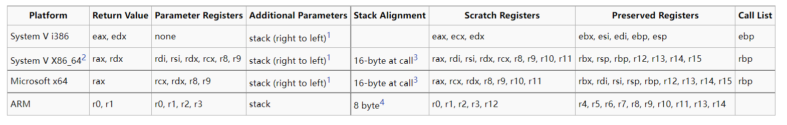
为了实现函数的递归调用调用方与被调方需要就参数如何传递,寄存器如何保存,返回地址如何存放等问题做出一致的约定,即我们需要一个一致的、稳定的栈帧布局。这种约定(保存寄存器,局部变量,返回地址的位置和顺序,对齐要求等)即为Calling convetion。上图即为一些常见架构的Calling convention这里我们通过汇编来观察x86下的C Calling convention。每次函数执行前都会有一段prologue code,即每当执行call指令调将eip即下一条要执行的指令的地址压栈并跳转至函数内后。首先会将ebp压栈,然后将当前esp复制到ebp,作为当前函数栈帧的起始位置,保存某些寄存器的值然后下移esp来获得新的栈空间。相关汇编代码如下:
 1
 2
 3
 4
 5
 6
 7
 8
 9
10
11
12
13
14
15
16
17
|
void
test_backtrace(int x)
{
f0100040:	f3 0f 1e fb          	endbr32
f0100044:	55                   	push   %ebp
f0100045:	89 e5                	mov    %esp,%ebp
f0100047:	56                   	push   %esi
f0100048:	53                   	push   %ebx
f0100049:	e8 7e 01 00 00       	call   f01001cc <__x86.get_pc_thunk.bx>
f010004e:	81 c3 ba 22 01 00    	add    $0x122ba,%ebx
f0100054:	8b 75 08             	mov    0x8(%ebp),%esi
	cprintf("entering test_backtrace %d\n", x);
f0100057:	83 ec 08             	sub    $0x8,%esp
f010005a:	56                   	push   %esi
f010005b:	8d 83 b8 f8 fe ff    	lea    -0x10748(%ebx),%eax
f0100061:	50                   	push   %eax
f0100062:	e8 e3 0a 00 00       	call   f0100b4a <cprintf>
|
于是,我们得到了如下图所示的一致且稳定的栈帧内存布局,从而可以进行递归的回溯。
 1
 2
 3
 4
 5
 6
 7
 8
 9
10
11
12
13
14
15
16
|
		       +------------+   |
		       | arg 2      |   \
		       +------------+    >- previous function's stack frame
		       | arg 1      |   /
		       +------------+   |
		       | ret %eip   |   /
		       +============+
		       | saved %ebp |   \
		%ebp-> +------------+   |
		       |            |   |
		       |   local    |   \
		       | variables, |    >- current function's stack frame
		       |    etc.    |   /
		       |            |   |
		       |            |   |
		%esp-> +------------+   /
|
Exercise 11要求我们打印调用占相关的信息,根据上图很容易写出kern/monitor.c中mon_backtrace函数代码如下:
 1
 2
 3
 4
 5
 6
 7
 8
 9
10
11
12
13
14
15
16
17
18
19
20
21
22
23
24
|
int mon_backtrace(int argc, char **argv, struct Trapframe *tf)
{
	// Your code here.
	uint32_t ebp = read_ebp();
	uint32_t *p;
	cprintf("Stack backtrace:\n");
	while(ebp != 0) {
		p = (uint32_t *)ebp;
		cprintf("ebp %08x  ", ebp);
		cprintf("eip %08x  ", p[1]);
		cprintf("args %08x ", p[2]);
		cprintf("%08x ", p[3]);
		cprintf("%08x ", p[4]);
		cprintf("%08x ", p[5]);
		cprintf("%08x\n",p[6]);
        if (debuginfo_eip(p[1], &info) == 0) {
            int fn_offset = p[1] - info.eip_fn_addr;
            cprintf("%s:%d: %.*s+%d\n", info.eip_file, info.eip_line, info.eip_fn_namelen, info.eip_fn_name, fn_offset);
        }
		ebp = p[0];
		ebp = p[0];
	}
	return 0;
}
|